source: http://www.doitpoms.ac.uk/tlplib/beam_bending/printall.php
Conten:ts
Main pages
Additional pages
Aims
On completion of this tutorial package, you should:
- Understand the stress distribution within beams subject to bending or torsion.
- Be familiar with the concepts of the radius of curvature of a section of a beam (and its reciprocal, the curvature), second moment of area, polar moment of inertia, beam stiffness and torsional stiffness.
- Be able to calculate the moments acting in a beam subject to bending or torsion.
- Be able to calculate the deflections of a beam on bending and the angle of twist of a bar under torsion.
- Be able to predict the effect of plastic deformation, at least with simple beam geometry.
Before you start
There are no specific prerequisites for this TLP, but it would be useful to be familiar with stress and strain , elastic strain and Plastic deformation , Young modulus , E and yield stress , σY. While a basic knowledge of mechanical deformation is assumed, this teaching and learning package covers all the fundamentals of beam mechanics.
Introduction
Beam stiffness is an important concept for many types of structure, particularly those with slender shapes. Inadequate beam stiffness can lead to large deflections, and may also cause high localised stresses and a danger of failure in that region. In addition to bending moments, such structures may be subjected to twisting, or torsional moments (torques). In fact, virtually all structures, including buildings and many natural structures (trees, bones etc) are commonly subjected to significant applied moments. It is important to recognise the roles of structural shape, applied loads and material properties when predicting the resultant moments, deflections and stress distributions. The aim of this TLP is to provide the necessary information to allow such bending and torsional moments, deflections (both elastic and elastoplastic) and stress distributions to be predicted and understood.
Pole-vaulting
Pole vaulting as an athletic activity dates back to the ancient Greeks. Modern competition started around the turn of the 20 th century, when the Olympic Games were restarted. A sharp increase in the achievable height coincided with the advent of composite (fibreglass) poles, about 50 years ago. These are sufficiently strong and flexible to allow substantial amounts of energy (kinetic energy of the athlete) to be transformed into elastic strain energy stored in the deformed pole, and subsequently transformed again into potential energy (height of the athlete) as the pole recovers elastically. The mechanics of beam bending is clearly integral to this operation.
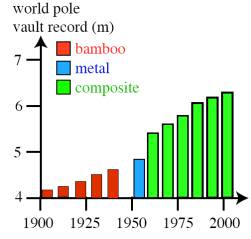

The sharp increase in achievable height that coincided with the switch to composite poles was due to a change in the mechanics of pole vaulting. Bamboo or metal poles with sufficient flexibility to allow significant energy storage would, respectively, be likely to fracture or plastically deform.
Visual inspection of a bent pole (see photo) is all that's needed to estimate the distribution of axial strains (and hence stresses) within its cross-section. The pole has a diameter of about 50 mm and it can be seen in the photo that it is being bent to a (uniform) radius of curvature, R , of the order of 1 m (~ length of the athlete's legs!). Considering a section of unit length (unstrained) in the diagram below, the angle θ (~tan θ ) ≈ 1/R after bending (where R is the radius of curvature). From the two similar triangles in the diagram, θ is also given by the surface strain ε divided by r , the radius of the pole . The surface strain, ε, is thus given by the ratio r / R , which has a value here of about 2.5 %. This strain is compressive on the "inside" surface of the pole (coloured blue) and tensile on the "outside" surface (coloured red).
The stresses induced by such bending can be high. The axial stress is given by the product of Young's modulus, E, and strain, ε.
σ =E ε = E r / R
For example, assuming the composite to have an axial stiffness of ~ 40 GPa, the axial stresses at the inside and outside surfaces of the pole must be about 2.5 % of this, ie ~±1 GPa. Composites are able to sustain such high stresses, although it's not unknown for vaulting poles to fracture.
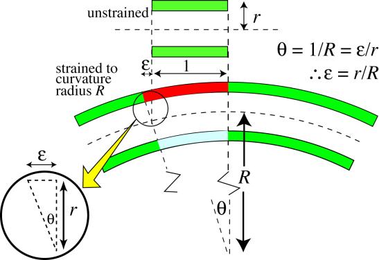
Strains induced during bending of a pole by the application of a bending moment M.
Bending moments and beam curvatures
Bending moments are produced by transverse loads applied to beams. The simplest case is the cantilever beam , widely encountered in balconies, aircraft wings, diving boards etc. The bending moment acting on a section of the beam, due to an applied transverse force, is given by the product of the applied force and its distance from that section. It thus has units of N m. It is balanced by the internal moment arising from the stresses generated. This is given by a summation of all of the internal moments acting on individual elements within the section. These are given by the force acting on the element (stress times area of element) multiplied by its distance from the neutral axis, y .
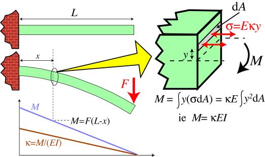
Balancing the external and internal moments during the bending of a cantilever beam
Therefore, the bending moment, M , in a loaded beam can be written in the form
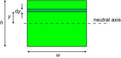
The concept of the curvature of a beam, κ, is central to the understanding of beam bending. The figure below, which refers now to a solid beam, rather than the hollow pole shown in the previous section, shows that the axial strain, ε, is given by the ratio y / R . Equivalently, 1/R (the "curvature", κ ) is equal to the through-thickness gradient of axial strain. It follows that the axial stress at a distance y from the Neutral axis of the beam is given by
σ = E κ y
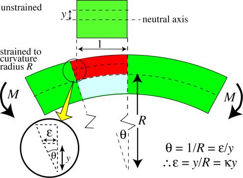
Relation between the radius of curvature, R, beam curvature, κ , and the strains within a beam subjected to a bending moment.
The bending moment can thus be expressed as
This can be presented more compactly by defining I (the second moment of area , or "moment of inertia") as
The units of I are m 4 . The value of I is dependent solely on the beam sectional shape. Click here to see how I is calculated for two simple shapes.
The moment can now be written as
M = κ E I
These equations allow the curvature distribution along the length of a beam (ie its shape), and the stress distribution within it, to be calculated for any given set of applied forces. The following simulation implements these equations for a user-controlled beam shape and set of forces. The 3-point bending and 4-point bending loading configurations in this simulation are SYMMETRICAL, with the upward forces, denoted by arrows, outside of the downward force(s), denoted by hooks
Note: This animation requires Adobe Flash Player 8 and later, which can be downloaded here.
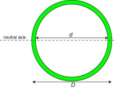
A fruitful approach to designing beams which are both light and stiff is to make them hollow. Calculation of the second moment of area for hollow beams is very straightforward, since it is obtained by simply subtracting the I of the missing section from that of the overall section. For example, that for a cylindrical tube is given by
Maximising the beam stiffness
The product EI is termed the "beam stiffness", or sometimes the "flexural rigidity". It is often given the symbol Σ. It is a measure of how strongly the beam resists deflection under bending moments. It is analogous to the Young's modulus in uniaxial loading (with the curvature being analogous to the uniaxial strain and the bending moment being analogous to the uniaxial stress). For a given material, the beam stiffness is maximised by maximising the value of I . This is done by using sectional shapes for which most of the sectional area is remote from the neutral axis.
For example, a beam of square cross-section is stiffer than a circular beam with the same area, since a circle has a larger proportion of the section near the neutral axis. A hollow square section is even stiffer. Taking this rationale still further leads to I-section beams and sandwich panels.
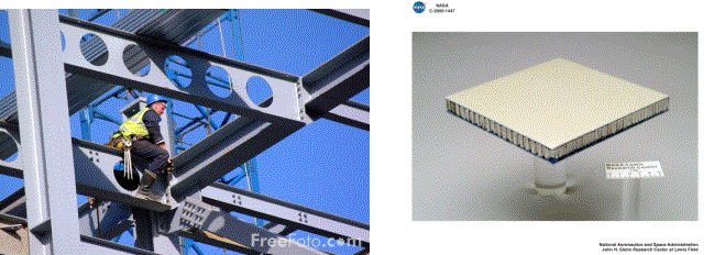
I-beams are commonly used in construction of buildings. Sandwich panels are also in extensive use, for example in surf-boards, aircraft, skis etc
Beam deflections from applied bending moments
As illustrated in the diagram below, the beam curvature, κ, is approximately equal to the second derivative (curvature) of the neutral axis line (dotted line in diagram)
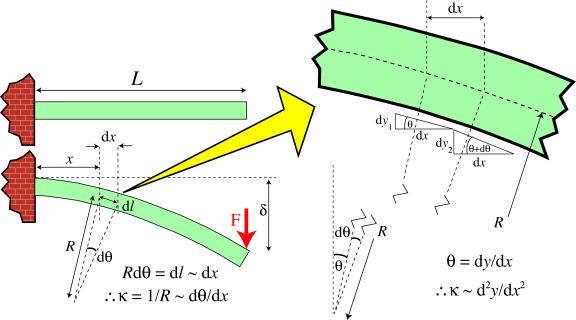
The approximation involved in equating beam curvature to the curvature of the neutral axis of a beam.
It follows that
Since the moment at the section concerned can also be written, for a cantilever beam, as
it follows that
This second order differential equation can be integrated (twice), with appropriate boundary conditions, to find the deflection of the beam at different points along its length. For a cantilever beam, this operation is shown below.


which can be rearranged to give
For example, at the loaded end ( x = L ), this gives
The corresponding operation for symmetrical 3-point bending can be seen by clicking here .
Twisting moments (torques) and torsional stiffness
Torsion is the twisting of a beam under the action of a torque (twisting moment). It is systematically applied to screws, nuts, axles, drive shafts etc, and is also generated more randomly under service conditions in car bodies, boat hulls, aircraft fuselages, bridges, springs and many other structures and components. A torque, T , has the same units (N m) as a bending moment, M . Both are the product of a force and a distance. In the case of a torque, the force is tangential and the distance is the radial distance between this tangent and the axis of rotation.
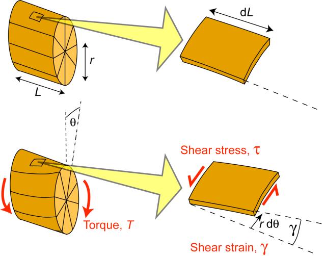
Torsion of a Cylindrical Bar
Torsion of a cylindrical bar is illustrated in the figure. It can be seen that the shear strain in an element of the bar is given by
This equation applies both at the surface of the bar, as shown, and also for any other radial location, using the appropriate value of r . Clearly, the shear strain varies linearly with r , from zero at the centre of the bar to a peak value at the free surface.
The shear stress, τ, at any radial location, is related to the shear strain by
where G is the shear modulus. It follows that
The torque, T , can therefore be written as
As for the beam bending case, the geometrical integral is represented as a (polar) second moment of area
For a solid cylinder of diameter w , this can be written as
The torque is thus given by
Comparing this equation with the corresponding one for beam bending
it can be seen that the torsional analogue for the curvature of a bent beam is the rate of twist along the length of the bar. This can be measured experimentally, although not quite so easily as a curvature (because the macroscopic shape of the bar does not actually change - at least when it is straight - see next page for an important example of a case when it is NOT straight).
Springs
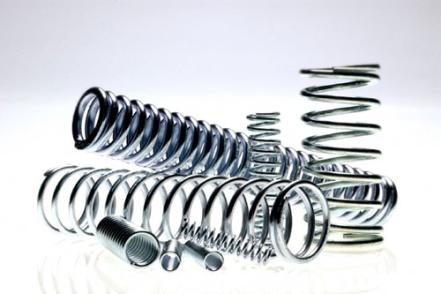
A collection of assorted springs
An interesting example of torsion is provided by the deformation that takes place during the loading of springs (torsional coils). Of course, these have a wide range of engineering applications. They are normally made of (high yield stress) metals. (Ceramics are too brittle, while polymers are insufficiently stiff: fibre composites are also unsuitable - see below.) When a spring is loaded (compressed or extended), the deformation experienced by the wire is one of pure torsion. This is illustrated in the diagram below.
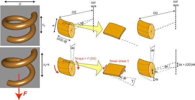
Illustration of how the application of an axial load, F, to a spring generates torsional deformation of the wire and hence axial extension of the spring.
The torque acting on the wire is given by
in which F is the axial force and D is the coil diameter. It can be shown ( click here ) that the shear stress within the wire (at a distance r from the core) is given by
in which I is the bending second moment of area (NOT the polar moment), and the shear strain in the wire is related to the change in axial extension of one turn of the coil, s , by the expression
Measurement of the extension (per turn) of a spring, as a function of the applied force (first carried out systematically by Robert Hooke , in his pioneering work on the nature of elasticity) is a very convenient method of obtaining elastic constants. The ratio of τ to γ , obtained from the above equations, gives the shear modulus, G . The loading geometry is such that a large axial extension (per turn) is generated, while the strains within the material remain low, particularly for springs with a large ratio of D to w . Of course, this is exactly why springs are of practical use - they accommodate large deflections or displacements without the material being strained beyond its elastic limit (which is small for all materials except rubbers).
It's interesting to note why springs are not normally made of fibre composites. The natural orientation for the fibres would be along the length of the rod (wire) to be formed into a coil. However, these fibres would have very little effect on the shear modulus in a transverse section of the rod, which is the property that controls the elastic extensions of the spring. It might as well have been made solely of the polymeric matrix (although such springs have a very low stiffness). It's only by winding fibres into the hoop direction of the rod that the shear stiffness of transverse sections would be boosted. However, this is impractical, at least for anything but very large scale springs, since it would require the fibres to adopt higher curvatures than would normally be possible.
Plastic deformation during beam bending

If the stresses within a beam exceed the elastic limit, then plastic deformation will occur. This can dramatically change the behaviour. Consider a material exhibiting elastic - perfectly plastic behaviour (ie no work-hardening), as shown below.
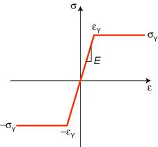
Stress-strain curve for an elastic-perfectly plastic material.
Stress and strain distributions before and after applying the moment are shown below. In the outer regions of the beam, the stress will be capped at σY, although the strain will continue to increase linearly with distance from the neutral axis, as in the elastic case. The curvature (strain gradient), κ, induced by a given moment, M, will now be greater, since this increase will be required in order to bring the internal moment back up to the level of the applied moment - i.e. bending will increase.
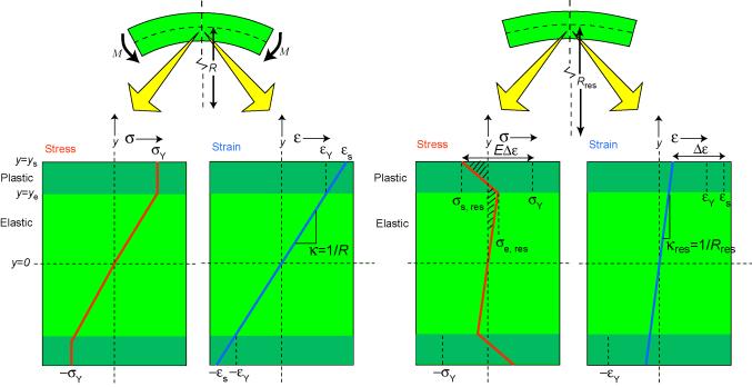
Distributions of stress and strain within a beam before and after application of a moment sufficiently large to cause plastic deformation
A further difference is observed on removal of the applied moment, since the beam will now retain a residual curvature , κres , as a result of the plastic deformation. This is due to the presence ofresidual stresses . The residual curvature can be calculated, using the fact that the beam is subject to no applied force. It follows that the residual stress distribution must satisfy a force balance , so that
which is equivalent to the shaded areas in the diagram being equal. Since the change in stress (at any value of y ) on removing the applied moment is given by the change in strain at that depth times the modulus (eg = E Δε at y = ys � see diagram), these equations allow the residual stress distribution to be established. The following expressions can be obtained ( click here ) for the thickness of the elastic core, the residual curvature, the surface residual stress and the residual stress at the limit of the elastic core.
Of course, the picture may in practice be complicated by work hardening, more complex sectional geometries, non-prismatic beams etc, but the same principles still apply. Incidentally, it may be noted that, in addition to the force balance, the residual stress distribution in an unloaded beam must also satisfy a moment balance , so that
However, the symmetry of the tensile and compressive sides of the beam ensures that this condition is satisfied, so it is not involved in the solution procedure in this case. In other cases, however, in which the neutral axis is not a plane of symmetry, this condition may also need to be invoked in order to find the solution.
The plastic deformation behaviour of a prismatic beam, with a symmetrical, rectangular section, made of a metal exhibiting no work hardening, can be explored using the plastic version of the beam bending simulation presented in an earlier section.
Note: This animation requires Adobe Flash Player 8 and later, which can be downloaded here.
Summary
You should now understand the basic principals of bending and torsion. You should be able to predict how a beam will respond elastically to a bending moment, from a knowledge of the Young's modulus, E , and the sectional geometry of the beam (from which the second moment of area, I , is derived). You should understand the relationship between the (local) bending moment, M , the beam stiffness (flexural rigidity), EI , and the resultant (local) curvature, κ.
The concept of torsion has been introduced, with the analogue of the bending moment being a torque, T , and the analogue of the curvature being the rate of twist of the beam, θ / L . The elastic constant controlling the behaviour is the shear modulus, G , and the sectional geometry analogue of the second moment of area, I , is the polar second moment of area, IP.
You should also have an appreciation of the nature of the stress distribution within an elastically deformed beam and you should understand that, for a metallic beam, it's possible that these stresses could exceed the yield stress, σY , so that plastic deformation could take place. In this case, there is a change in the relationship between the applied moment and the resultant curvature (so that a given increase in moment gives a larger increase in curvature). Furthermore, on removing the applied moment, the beam retains a residual curvature. Analogous phenomena can occur during torsion. These effects can be quantitiatively predicted.
Some implications of these analyses for the design of components and structures subject to bending moments and torques have been briefly outlined.
Questions
Quick questions
You should be able to answer these questions without too much difficulty after studying this TLP. If not, then you should go through it again!
- How do the axial stresses within a vaulting pole vary with distance from the neutral axis?
- It is important to maximise the beam stiffness when attempting to minimise the deflection of a beam (of given mass). Which of the following shapes, all with dimensions such that they have the same cross-sectional area, will have the highest beam stiffness?
- In which of the following situations is torsion occurring?
- How can the stress distribution in an elastoplastic beam undergoing bending be predicted?
Deeper questions
The following questions require some thought and reaching the answer may require you to think beyond the contents of this TLP.
- Which of the following sectional shapes will give the highest beam stiffness?
a Hollow tube of outer diameter 15 cm and inner diameter 14 cm
b I-beam with a central section 11 cm high by 2 cm wide and flanges 2 cm high by 10 cm wide (giving a total height of 15 cm) - A solid rectangular section beam of length, L = 100 cm, height, h = 5 cm and width, w = 1 cm, is loaded under symmetrical 4-point bending, with 1000 N downward forces applied at 40 cm in from both ends of the bar, which is supported at both ends. A deflection of 5 mm is measured at the centre of the beam. Using these data, calculate the Young's modulus of the beam. From your answer, suggest a likely material for the beam.
- Calculate the shear modulus, G , of a material supplied in the form of a hollow tube (length 100 cm, outer diameter 5 cm, wall thickness 0.1 cm), given that, when it is subjected to an applied torque of 1000 N m, an angular twist of 0.10 radians is generated.
Going further
Books
- S.P. Timoshenko, J.N. Goodier, Theory of Elasticity, McGraw-Hill International Editions, Third Edition, 1970.
- J.M. Gere, Mechanics of Materials , Nelson Thornes, Fifth SI Edition, 2001.
Websites
- Simulation showing the stress distribution in 3-point bending: http://teaching.ust.hk/~mech101/3%20point%20bending.htm
- Video of the 3-point bending of a brass beam: http://www.doitpoms.ac.uk/vidlib/full_record.php?id=14
- Stress distribution In a polycarbonate bar undergoing 3-point bending: http://www.doitpoms.ac.uk/vidlib/full_record.php?id=36
- 3-point bending simulation for a sandwich beam: http://mms.ensmp.fr/Mms_scripts/Beam/index.php
- Simulation showing the stress distribution in 4-point bending: http://teaching.ust.hk/~mech101/4_point_bending.htm
- Stress distribution In a polycarbonate bar undergoing 4-point bending: http://www.doitpoms.ac.uk/vidlib/full_record.php?id=40
- Simulation of shear, moment and deflection on application of different forces to a beam: http://www.engr.umd.edu/HAMLET/BeamAnalysis/
- Sandwich panels: http://oneoceankayaks.com/Sandcore.htm
- The torsional pendulum: http://farside.ph.utexas.edu/teaching/301/lectures/node139.html
- Granta Design case studies by a former Cambridge student
Symmetrical 3-point bending
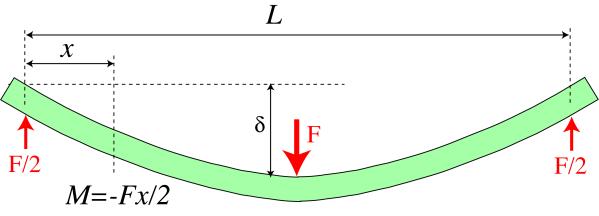
Symmetrical 3-point bend loading
The bending moment is given by
It follows that
and the integration procedures lead to


so the equation for the deflection is
and deflection of the centre of the beam is given by
Derivation of equations
Consider the small elemental length of the wire shown in the figure, subtending an angle dβ at the axis of the coil. The torsional shear stress within the wire, τ, can be found by noting that it varies linearly with distance from the centre of the wire ( τ = κ r , where κ is an unknown constant and r is the distance of the element from the centre of the wire) . The torque can now be expressed in terms of internal forces in the wire. The force in an individual element of the wire is given by the torsional shear stress, τ, multiplied by the area of the element, 2 π r dr . Therefore, the elemental torque is simply this force multiplied by the distance of the element from the neutral axis of the wire, r . Summation of these elemental torques gives the total torque:
where I is the second moment of area for a solid cylinder (the wire), given by:
The local shear strain in the material is given by
in which dθ /dL is the rate of twist along the length of the wire. The incremental angle of twist of the wire is therefore related to the corresponding incremental rotation angle of the coil by
The axial displacement of the coil, due to the twisting of the elemental section, can therefore be written
The axial displacement associated with the twist in one complete turn of the coil is thus
The local shear strain in the wire is therefore related to the increase in spacing between adjacent turns in the coil by
Derivation of expressions
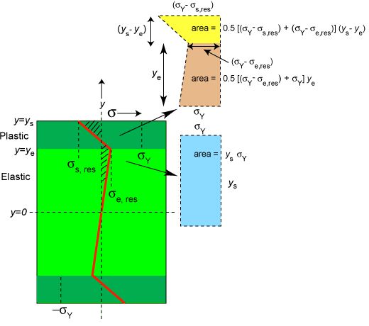
The force balance can in this case (see above figure) be written as
which simplifies to
Elastic unloading of the surface region gives

while the same condition applied at the limit of the elastic core leads to

Substitution of these two expressions for the stresses into the above equation obtained from the force balance then gives the equation
which can be simplified to
Calculating I for simple shapes
The second moment of area for a rectangular section beam of width w and thickness h is given by
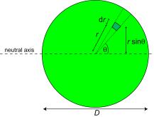
The corresponding operation for a circular cross-section of diameter D gives

Academic consultant: Bill Clyne (University of Cambridge)
Content development: Sonya Pemberton
Photography and video: Brian Barber and Carol Best
Web development: David Brook
Content development: Sonya Pemberton
Photography and video: Brian Barber and Carol Best
Web development: David Brook
DoITPoMS is funded by the UK Centre for Materials Education and the Department of Materials Science and Metallurgy, University of Cambridge.
Additional support for the development of this TLP came from the Worshipful Company of Armourers and Brasiers'
